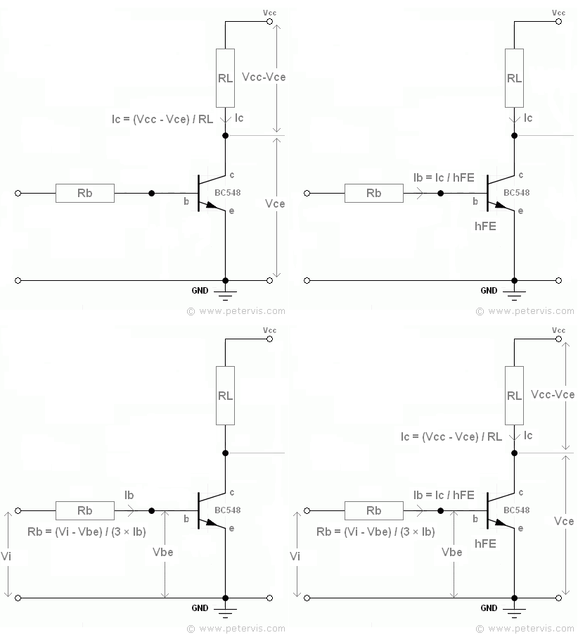

One of the most frequently used biasing circuits for a transistor circuit is with the self-biasing of the emitter-bias circuit were one or more biasing resistors are used to set up the initial DC values for the three transistor currents, ( I B ), ( I C ) and ( I E ). In this simple transistor biasing tutorial we will look at the different biasing arrangements available for a Common Emitter Amplifier. Base bias networks can be used for Common-base (CB), common-collector (CC) or common-emitter (CE) transistor configurations. Since the transistors Base bias currents are steady-state DC currents, the appropriate use of coupling and bypass capacitors will help block any biasing currents from other transistor stage affecting the bias conditions of the next. This steady-state or DC operating point is set by the values of the circuits DC supply voltage ( Vcc ) and the value of any biasing resistors connected the transistors Base terminal. The function of the “DC Bias level” is to correctly set the transistors Q-point by setting its Collector current ( I C ) to a constant and steady state value without any external input signal applied to the transistors Base. So how do we set this Q-point biasing of a transistor? – The correct biasing of the transistor is achieved using a process known commonly as Base Bias.īut before we start looking at the possible different transistor biasing arrangements, lets first remind ourselves of a basic single transistor circuit along with its voltages and currents as shown on the left.
#Transistor biasing calculator full
In other words, the output is available for the full 360 o of the input cycle. This mode of operation allows the output voltage to increase and decrease around the amplifiers Q-point without distortion as the input signal swings through one complete cycle. When a bipolar transistor is biased so that the Q-point is near the middle of its operating range, that is approximately halfway between cut-off and saturation, it is said to be operating as a Class-A amplifier. This central operating point is called the “Quiescent Operating Point”, or Q-point for short. The correct biasing point for a bipolar transistor, either NPN or PNP, generally lies somewhere between the two extremes of operation with respect to it being either “fully-ON” or “fully-OFF” along its DC load line.

Some off the cuff rules that usually work so long as your bias resistors allow enough current flow generally means that you treat R1 and R2 as a voltage divider and find an approximate DC setpoint from that.The steady state operation of a transistor depends a great deal on its base current, collector voltage, and collector current values and therefore, if the transistor is to operate correctly as a linear amplifier, it must be properly biased around its operating point.Įstablishing the correct operating point requires the selection of bias resistors and load resistors to provide the appropriate input current and collector voltage conditions. If your input voltage source has an output impedance somewhere in between the two extreme cases I give (0 and infinite impedance) then you'll need to add that into the circuit and start crunching the numbers/equations.

In that case, what the others post is correct. In that case, the bias resistors you see in your diagram are what will determine the DC set point of Vb is.

This means that DC will be blocked and AC will pass through. In that case, all of the bias resistors really don't matter because the input voltage will drown out their effect.Īlternately, something like this is commonly driven by a capacitively coupled source. If it's low, then it's as if you're applying a true voltage source to Vb. If an op-amp or a similar amplifier stage drives Vb, then the output impedance should be quite low. Without it you can't really know for sure. You would really need to know the output resistance of the input voltage source to Vb.


 0 kommentar(er)
